
RAMCO Equipment Fluorescent Penetrant Inspection System – Inspection Booths
Fluorescent Penetrant Inspection
BACKGROUND
Fluorescent Penetrant inspection is a widely applied method used to locate surface-breaking defects in all non-porous materials (metals, plastics, or ceramics). FPI is used to detect casting and forging defects, cracks, and leaks in new products, and fatigue cracks on in-service components.
FPI is based upon capillary action, where low surface tension fluid penetrates into clean and dry surface-breaking discontinuities. Penetrant may be applied to the test component by dipping, spraying, or brushing. After adequate penetration time has been allowed, the excess penetrant is removed, and a developer is applied. The developer helps to draw penetrant out of the flaw where a visible indication becomes visible to the inspector. Inspection is performed under ultraviolet light.
Dye penetrant inspection
1. Section of material with a surface-breaking crack that is not visible to the naked eye.
2. Penetrant is applied to the surface.
3. Excess penetrant is removed.
4. Developer is applied, rendering the crack visible.
Below are the main steps of Fluorescent Penetrant Inspection:
1. Pre-cleaning:
The test surface is cleaned to remove any dirt, paint, oil, grease or any loose scale that could either keep penetrant out of a defect, or cause irrelevant or false indications. The end goal of this step is a clean surface where any defects present are open to the surface, dry, and free of contamination. Surface Preparation prior to liquid penetrant application in accordance with ASTME 1417 states, “All surfaces to be examined shall be clean, dry, and free of soils, oil, grease, paint and other coatings, corrosion products, scale, smeared metal, welding flux, chemical residues, or any other material that could prevent the penetrant from entering discontinuities, suppress dye performance, or produce unacceptable background.”
2. Application of Penetrant:
The penetrant is then applied to the surface of the item being tested. The penetrant is allowed time to soak into any flaws. The soak time mainly depends upon the material being testing and the size of flaws sought.
3. Excess Penetrant Removal:
The excess penetrant is then removed from the surface. Removal method is controlled by the type of penetrant used. Water-washable, solvent-removable, lipophilic post-emulsifiable, or hydrophilic post-emulsifiable are the common choices. This process must be performed under controlled conditions so that all penetrant on the surface is removed (background noise), but penetrant trapped in real defects remains in place.
4. Application of Developer:
After excess penetrant has been removed a white developer is applied to the sample. Developer should form a thin, even coating on the surface. The developer draws penetrant from defects out onto the surface to form a visible indication, a process similar to the action of blotting paper. Any colored stains indicate the positions and types of defects on the surface under inspection.
5. Inspection:
The inspector will use visible light with adequate intensity (100 foot-candles is typical) for visible dye penetrant. Ultraviolet (UV-A) radiation of adequate intensity (1,000 micro-watts per centimeter squared is common), along with low ambient light levels (less than 2 foot-candles) for fluorescent penetrant examinations. Inspection of the test surface should take place after a 10 minute development time. This time delay allows the blotting action to occur. The inspector may observe the sample for indication formation when using visible dye, but this should not be done when using fluorescent penetrant. Also of concern, if one waits too long after development the indications may “bleed out” such that interpretation is hindered.
APPLICATION
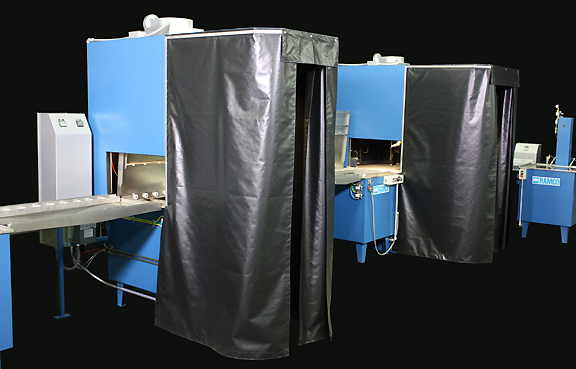
Semi-Automated FPI System with Inspection Booth and Post-Cleaning
The system below incorporates a complete semi-automated FPI system with post cleaning. The application is for a water-washable penetrant as per ASTM E 1417. The process consists of nine steps – Penetrant, Dwell, Spray Rinse, Hot Air Dry, Dry Developer, Inspection Booth, Post- Cleaning (Wash-Rinse-Dry). Viewing booths are built for both the spray rinse and for final inspection operations to ensure accurate penetrant removal as well as visual inspection.
The line runs left to right and processes a wide variety of aerospace components loaded into baskets placed on a transport elevator. This semi-automated line uses standard RAMCO elevator within each processing chamber. The elevator is used to transport the work into and out of the chamber but its most important function is to continuously move the work as required within selected processing zones. This function is especially effective in the spray rinsing, drying prior to developer, and all post cleaning operations.

The baskets are placed on the first transport elevator of the line. From that point on everything is transferred over roller conveyor sections – there is no lifting/lowering required. The FPI rinsing module includes strategically placed spray headers (specific nozzle locations and patterns) with zoned platform oscillation between the headers to effectively remove penetrant. Adequate hot water is brought to the system within the temperature and pressure limits set by the specifications on penetrant removal. Water detailing and air blow-off guns are use to ensure that any final traces of penetrant and excess water have been removed.
Next in line is a RAMCO Hot Air Knife Dryer. The key to the drying process is using the elevator to produce changing flow patterns. This in turn results in a dynamic drying mode (i.e. platform oscillation combined with high volume hot air flow) that allows for better drying at lower temperatures. See dynamic flow combination for further information.
After drying the basket is transferred to the Dry Developer Cloud Burst module with integrated dust collector and then into the adjacent Inspection Booth as shown below.
